After messing around with two instrument clusters, I figured out how to fix the problem of the “Check Gauges” and/or “Low Fuel” light stuck on. The cause is bad solder joints around the warning light driver IC (chip). The fix is very simple, the cost of the tools is very low, so I would encourage you to fix it yourself and save some money if you’re handy with a soldering iron. By the way, this fix also applies to probably any 1988-93 Pontiac Grand Prix instrument cluster.
Repairing your instrument cluster yourself is cheap & easy. If you have the tools, it’s pretty much a FREE repair. The hardest part is getting the instrument cluster out of the car and then putting it back in. Read on to learn how to repair it yourself.
- Tools Required:
- Pencil tip soldering iron
- 60/40 tin/lead solder
- Small knife
- Screwdriver or wrench with TORX T-15 bit
Repair Instructions:
Here are the instructions for fixing your instrument cluster yourself. It’s actually a simple job and the tools to fix it don’t cost much at all either. Clicking on any picture will let you view a larger version.
- Remove the instrument cluster from the car.
- To remove the cluster:
- Remove one 7mm screw from underneath the dash pad through the access hole on the inside top of the glove box.
- Remove the 2 phillips screws holding the HUD unit.
- Disconnect HUD electrical connector and remove HUD.
- Remove the 2 phillips screws along the top inside edge of the instrument cluster area.
- Lift up the dash pad with enough force to overcome clips, pull slightly towards you and remove the dash pad.
- Remove the three screws holding the HUD tray and move it out of the way.
- Remove four 7mm screws holding the instrument cluster on. Two on top, one on the bottom behind the wiper switches and the other behind the headlight switches.
- Disconnect the wire harness on the left side and lift out the cluster, make sure to push in the trip odometer reset button to clear the plastic cluster visor on the right side.
- Remove the 5 silver TORX T-15 screws on the back of the cluster.
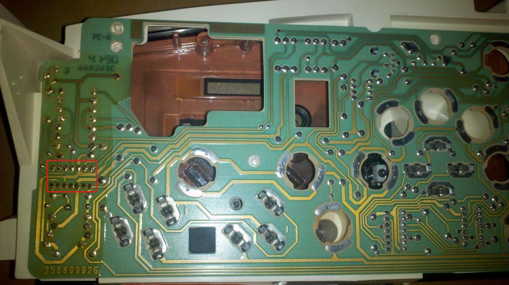
If your cluster is original, there should be a black plastic cover that you will need to remove. Place the cluster face down on a soft cloth in order to prevent scratching the clear acrylic lens. - Locate the IC, it is on the edge to your left (the opposite side of the connector) of the circuit board. It is a 14-pin DIP IC, but all you will see are TWO horizontal rows of 7 pins soldered to the circuit board.
- Using a small knife, carefully scrape off the clear/brownish lacquer coating from the solder around the pins. I found this step necessary because the solder tended to stick to the lacquer coating making solder bridges, so you will save yourself some headaches if you scrape the stuff off. Be sure not to scrape through any traces or through the green coating.
- Using the pencil tip soldering iron, resolder all 14-pins.
- Plug in the connector and turn on the ignition to verify that your cluster is working correctly and no lights are now stuck on.
If everything is now okay, reassemble your dash and you’re finished!